


Multi-mode optical fiber
Multi-mode optical fiber (multimode fiber or MM fiber or fibre) is a type of optical fiber mostly used for communication over short distances, such as within a building or on a campus. Typical multimode links have data rates of 10 Mbit/s to 10 Gbit/s over link lengths of up to 600 meters-more than sufficient for the majority of premises applications.
Applications
The equipment used for communications over multi-mode optical fiber is less expensive than that for single-mode optical fiber. Typical transmission speed and distance limits are 100 Mbit/s for distances up to 2 km (100BASE-FX), 1 Gbit/s to 220-550 m (1000BASE-SX), and 10 Gbit/s to 300 m (10GBASE-SR), such as SR 10G SFP+ transceivers, 10G XFP transceivers, 10G X2 transceivers and other 10G modules.
Because of its high capacity and reliability, multi-mode optical fiber generally is used for backbone applications in buildings. An increasing number of users are taking the benefits of fiber closer to the user by running fiber to the desktop or to the zone. Standards-compliant architectures such as Centralized Cabling and fiber to the telecom enclosure offer users the ability to leverage the distance capabilities of fiber by centralizing electronics in telecommunications rooms, rather than having active electronics on each floor.
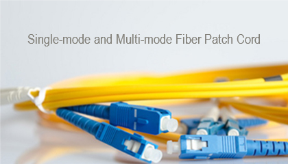
Comparison with single-mode fiber
The main difference between multi-mode and single-mode optical fiber is that the former has much larger core diameter, typically 50-100 micrometers; much larger than the wavelength of the light carried in it. Multi-mode fiber has higher "light-gathering" capacity than single-mode fiber. In practical terms, the larger core size simplifies connections and also allows the use of lower-cost electronics such as light-emitting diodes (LEDs) and vertical-cavity surface-emitting lasers (VCSELs) which operate at the 850 nm and 1300 nm wavelength (single-mode fibers used in telecommunications operate at 1310 or 1550 nm and require more expensive laser sources. Single mode fibers exist for nearly all visible wavelengths of light). However, compared to single-mode fibers, the multi-mode fiber bandwidth-distance product limit is lower. Because multi-mode fiber has a larger core-size than single-mode fiber, it supports more than one propagation mode; hence it is limited by modal dispersion, while single mode is not. The LED light sources sometimes used with multi-mode fiber produce a range of wavelengths and these each propagate at different speeds. In contrast, the lasers used to drive single-mode fibers produce coherent light of a single wavelength. This chromatic dispersion is another limit to the useful length for multi-mode fiber optic cable. Because of their larger core size, multi-mode fibers have higher numerical apertures which means they are better at collecting light than single-mode fibers. Due to the modal dispersion in the fiber, multi-mode fiber has higher pulse spreading rates than single mode fiber, limiting multi-mode fiber’s information transmission capacity. Single-mode fibers are most often used in high-precision scientific research because the allowance of only one propagation mode of the light makes the light easier to focus properly. Jacket color is sometimes used to distinguish multi-mode fiber optic patch cords/cables from single-mode, but it cannot always be relied upon to distinguish types of cable. The standard TIA-598C recommends, for civilian applications, the use of a yellow jacket for single-mode fiber, and orange for 50/125 µm (OM2) and 62.5/125 µm (OM1) multi-mode fiber. Aqua is recommended for 50/125 µm "laser optimized" OM3 fiber.
Types
Multi-mode fibers are described by their core and cladding diameters. Thus, 62.5/125 µm multi-mode fiber has a core size of 62.5 micrometres (µm) and a cladding diameter of 125 µm. The transition between the core and cladding can be sharp, which is called a step-index profile, or a gradual transition, which is called a graded-index profile. The two types have different dispersion characteristics and thus different effective propagation distance.In addition, multi-mode fibers are described using a system of classification determined by the ISO 11801 standard - OM1, OM2, and OM3 - which is based on the modal bandwidth of the multi-mode fiber. OM4 (defined in TIA-492-AAAD) was finalized in August 2009, and was published by the end of 2009 by the TIA. OM4 cable will support 125m links at 40 and 100 Gbit/s.
For many years 62.5/125 µm (OM1) and conventional 50/125 µm multi-mode fiber (OM2) were widely deployed in premises applications. These fibers easily support applications ranging from Ethernet (10 Mbit/s) to Gigabit Ethernet (1 Gbit/s) and, because of their relatively large core size, were ideal for use with LED transmitters. Newer deployments often use laser-optimized 50/125 µm multi-mode fiber (OM3). Fibers that meet this designation provide sufficient bandwidth to support 10 Gigabit Ethernet up to 300 meters. Optical fiber manufacturers have greatly refined their manufacturing process since that standard was issued and cables can be made that support 10 GbE up to 550 meters. Laser optimized multi-mode fiber (LOMMF) is designed for use with 850 nm VCSELs which is widely used in MM SFP transceivers, including SPT-P851G-S5D, SPT-P854G-S3xD and so on.
The migration to LOMMF/OM3 has occurred as users upgrade to higher speed networks. LEDs have a maximum modulation rate of 622 Mbit/s because they can not be turned on/off fast enough to support higher bandwidth applications. VCSELs are capable of modulation over 10 Gbit/s and are used in many high speed networks.
VCSEL power profiles, along with variations in fiber uniformity, can cause modal dispersion which is measured by differential modal delay (DMD). Modal dispersion is an effect caused by the different speeds of the individual modes in a light pulse. The net effect causes the light pulse to separate or spread over distance, making it difficult for receivers to identify the individual 1's and 0's (this is called intersymbol interference). The greater the length, the greater the modal dispersion. To combat modal dispersion, LOMMF is manufactured in a way that eliminates variations in the fiber which could affect the speed that a light pulse can travel. The refractive index profile is enhanced for VCSEL transmission and to prevent pulse spreading. As a result the fibers maintain signal integrity over longer distances, thereby maximizing the bandwidth.
Comparison
Transmission Standards | 100 Mb Ethernet | 1 Gb (1000 Mb) Ethernet | 10 Gb Ethernet | 40 Gb Ethernet | 100 Gb Ethernet |
OM1 (62.5/125) | up to 550 meters(SX) | 220 meters(SR) | 33 meters(SR) | NOT SUPPORTED | NOT SUPPORTED |
OM2 (50/125) | up to 550 meters(SX) | 550 meters(SR) | 82 meters(SR) | NOT SUPPORTED | NOT SUPPORTED |
OM3 (50/125) | up to 550 meters(SX) | 550 meters(SR) | 300 meters(SR) | 100 meters | 100 meters |
OM4 (50/125) | up to 550 meters(SX) | 550 meters(SR) | >400 meters(SR) | 125 meters | 125 meters |
Tags:optical fiber, fiber optic cable, multimode fiber cable,singlemode fiber
— END —